Reverse engineering the RF protocol on a Kambrook Power Point Controller
433MHz remote control “power point controllers” are becoming more prevalent at bargain basement prices. These units consist of a single power point adapter and a radio frequency (RF) remote control allowing the device plugged into the power point adapter to be turned on and off remotely from distances up to approximately 30 meters. By hacking and replaying the 433MHz protocol, these cheap adapters can be safely controlled by a microcontroller system such as an Arduino. Being radio frequency, there is no physical connection to potentially lethal mains voltages and having passed the mandatory compliance checks there should be no threat to safety or from fire.

To demonstrate just how cheap these adapters are, you can pick up a three pack complete with remote control (Pictured above) from your local Bunnings Hardware store for $29.90 AUD. If $29.90 breaks the bank, a single outlet without remote control costs just $8.98 AUD. You don’t need the remote control when operating these devices from a foreign microcontroller, hence the remote control is superfluous.
Sold under the Kambrook & Bauhn brands, the RF3399/RF3405/RF3672/RF3689/RF4471R Power Point Controller appears to be made by Ningbo Comen Electronics Technology Co. Ltd.
The remote control consists of 10 buttons and a slider switch. There is a dedicated switch to turn on a power point controller (left hand side) and a different button to turn it off (right hand side) thus five appliances can be controlled. To further expand the system, the slider switch can select up to four groups of appliances, hence a total of twenty appliances can be controlled.
Each power point controller comes from the factory uncoded. Before use, the end user needs to hold the on button for five seconds until the indicator light starts flashing. The user can then press either the off or on button to assign this button/group to the power point controller and the code is stored away in non volatile EEPROM.
There are a range of methods for eavesdropping on the protocol communicated between the remote control and the power point adapter. One method can be to use a third party 433.92MHz receiver module. This has the advantage in that you don’t need to pull anything apart (boring), but there can be some jitter on the raw signal from the demodulator hindering efforts to obtain accurate timing information. Another way (much more exciting) is to pull the transmitter apart and probe the signal prior to modulation. Naturally, I decided to explore the later.
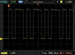
Examining the printed circuit board (PCB) suggested the device operated from either a microcontroller or ASIC (as expected the top of the IC has been ground off) and a separate 433.92MHz SAW resonator. The demodulated signal is present on pin 13 of the IC and is routed toward the SAW resonator via jumper wire J3 on the single sided PCB. This made an ideal location to probe for the signal. On a DSO the message looked like:

The message appeared to comprise of a series of short and long pulses. A short pulse was constructed from a 280uS wide pulse, followed by 300uS off period. The long pulse consisted of a 675uS wide pulse, followed by the same 300mS off period. With the timing down pat and a quick check the logic level was 5V and wouldn’t cause damage, I next reached for the logic analyser. My logic analyser has deeper memory than the DSO and is hence more suitable for decoding these longer, more complex messages.

Above is the waveform from one complete message – Group A, Unit 1 On – containing 48 bits or 6 bytes. When a button is pressed, the message is repeated five times. Then the button must be depressed.
I then proceed to decode a sample of messages in a bid to understand the decoding of the message. The result can be found in the table below.
| Group | Unit | Operation | Sync | Addr 1 | Addr 2 | Addr 3 | Data | Trailing |
| A | 1 | On | 01010101 | 00000000 | 01101101 | 11111101 | 00000001 | 11111111 |
| A | 1 | Off | 01010101 | 00000000 | 01101101 | 11111101 | 00000010 | 11111111 |
| A | 2 | On | 01010101 | 00000000 | 01101101 | 11111101 | 00000011 | 11111111 |
| A | 2 | Off | 01010101 | 00000000 | 01101101 | 11111101 | 00000100 | 11111111 |
| A | 3 | On | 01010101 | 00000000 | 01101101 | 11111101 | 00000101 | 11111111 |
| A | 3 | Off | 01010101 | 00000000 | 01101101 | 11111101 | 00000110 | 11111111 |
| A | 4 | On | 01010101 | 00000000 | 01101101 | 11111101 | 00000111 | 11111111 |
| A | 4 | Off | 01010101 | 00000000 | 01101101 | 11111101 | 00001000 | 11111111 |
| A | 5 | On | 01010101 | 00000000 | 01101101 | 11111101 | 00001001 | 11111111 |
| A | 5 | Off | 01010101 | 00000000 | 01101101 | 11111101 | 00001010 | 11111111 |
| B | 1 | On | 01010101 | 00000000 | 01101101 | 11111101 | 00010001 | 11111111 |
| C | 1 | On | 01010101 | 00000000 | 01101101 | 11111101 | 00100001 | 11111111 |
| D | 1 | On | 01010101 | 00000000 | 01101101 | 11111101 | 00110001 | 11111111 |
With all the hard work done, it was now time to write some code to replay the messages and check if it works.

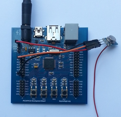
I used a garden variety TWS-BS 433.92MHz RF ASK Transmitter available from Little Bird Electronics for as little as $4.95 AUD or from Altronics at $7.95 AUD.
The TWS-BS-3 transmitter can be operated from a 1.5V to 12V supply. In this example, I run it from a 5 volt supply. The Data IN pin is connected to the PIC32′s RD0 pin.
After a little trial and error it appeared the controllers refused to play ball if the messages were not separated by more than 7mS.
It would also appear the trailing byte can be anything – it doesn't effect the operation of the unit.
A notable omission from the protocol is a checksum. It was found during testing, if the timing was a little slack, I could erroneously turn on a neighbouring unit or toggle the state off the unit I was intending on controlling.
The Source Code can be downloaded here for the Microchip PIC32MX440F512H.