Reverse engineering the 433MHz RF protocol on a 4 outlet powerboard
Sino Wealthy (Hong Kong) Limited manufacture a four outlet remote controlled power board sold under various brands including Click (Part No. CLKRCP4), PowerTran (Cat No. P-8119), PowerTech/Jaycar (Cat No MS6150) and Heller (Part No. RCS8888.) With 4 independently operated outlets controlled by a 433MHz RF remote control, it makes for an ideal candidate for basic home automation. Once the protocol is known, there is no need to penetrate the power board and fiddle with circuitry at potentially dangerous mains potentials. The end result is four standards compliant mains relay outputs that can be purchased off the shelf at a budget price.
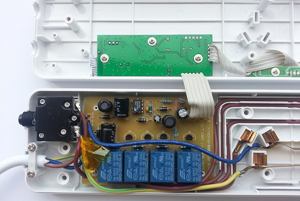
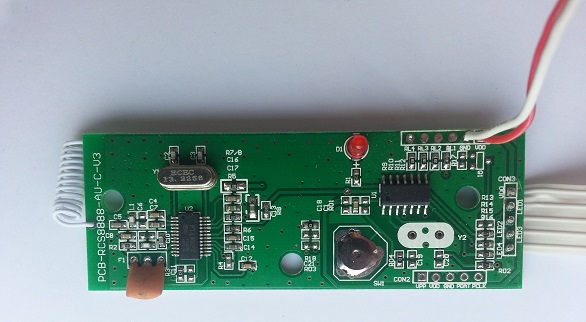
Having a peek in the power board shows it is made of two Printed Circuit Boards (PCBs). One includes an energy efficient non-isolated switcher integrated circuit (LNK304) to provide the 5 volts DC at 120mA to power the logic and four 10 amp 250 VAC relays to switch each outlet on and off. A six wire ribbon cable is used to connect this board to the 433MHz receiver comprising of a PT4301 433MHz OOK/ASK Receiver and micro-controller.

It is easy to identify a trace leading from the PT4301 that includes the asynchronous message to be decoded by the micro-controller. In fact, it even includes a test point. As the board is not isolated from the mains and is potentially hazardous to probe while connected, I went about de-soldering the 6 pin ribbon cable so I could power the RF decoder from a bench power supply and connect it safely to an oscilloscope and later – a logic analyser.

The remote control distributed with the board contains five buttons. There is a “all off” button, followed by buttons 1 to 4 used to toggle on and off each outlet. The power board ships uncoded from the factory and requires pairing before use. To pair, the end user presses the ‘coding’ button on the power board and then presses the “all off” button on the remote control. According to the manual, up to five remote controls can be used with a single power board.
In next to no time, I had captured my first message and proceeded to decode it:

When a button was held down, the 45mS long message was sent approximately every 50mS. The first check was to make sure each repeated message was identical. It was, so this made life much easier. Some, more secure remote controls may employ code hoping, making decoding and replay just a tad more difficult.
Closer examination of the actual message showed a series of shorter and longer positive pulses, all having the same period. I have assigned the short pulse a logic ’0′ and the long pulse a logic ’1′. Based on these assumptions, each message contains 34 bits.
Decoding the five buttons resulted with: